John Mathews & J. Ramsey Patent
JAMES W. TUFTS, OF MEDFORD, AND JONATHAN RAMSEY, OF BOSTON, MASSACHUSETTS; SAID RAMSEY ASSIGNOR TO SAID TUFTS.
SODA-WATER-DISPENSING APPARATUS.
SPECIFICATION forming part of Letters Patent No. 431,491, dated July 1, 1.890. Application filed January 24,1890. Serial No. 337,983. (No model.)
To all whom it may concern:
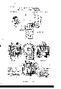
Be it known that we, JAMES W. TUFTS, of Medford, in the county of Middlesex and State of Massachusetts, and JONATHAN RAMSEY, of Boston, in the county of Suffolk and State aforesaid, have invented certain Improvements in Soda-Water-Dispensing Apparatus, of which the following is a full, clear, and exact description, reference being had to the accompanying drawings, making part of this specification, in which- Figure 1 is a sectional elevation of a portion of a soda-water dispensing apparatus, showing one of the sirup-cans provided with a measuring gate or faucet constructed in accordance with our invention, and the lever for operating the same from the outside of the casing. Fig. 2 is an enlarged vertical section of the measuring-faucet. Fig. 3 is a horizontal section of the same on the line as of Fig. 2. Fig. 4 is a front elevation of the measuring-faucet. Fig. 5 is a sectional elevation on the line y y of Fig. 4. Fig. 6 is a perspective view of the double-headed valve.
Our invention relates to certain improvements in the valve mechanism of sirup cans or tanks of soda-water-dispensing apparatus, and has for its object to provide a simple, durable, and effective measuring gate or faucet for said Sirup-cans which is adapted to be operated by a lever or handle.
To this end our invention consists in the combination, with a Sirup-can provided with an outlet-opening, of a gate or faucet having a measuring-chamber provided with a rocking double-headed valve adapted to alternately open and close the inlet and discharge openings of said chamber, said valve having a rock-shaft extending outside the chamber, and a spring for normally holding the valve in a position to close the outlet-opening of the measuring-chamber and simultaneously leave its inlet-aperture open, as hereinafter more particularly described; and our invention also consists in the combination, with a measuring gate or faucet provided with a rocking valve, as described, of an air-valve adapted to be operated at the proper time by the action of the Sirup-valve mechanism, whereby the necessary supply of air is admitted to the measuring-chamber to allow the free discharge of its contents.
In the said drawings, A represents a portion of the front of the marble or outer casing of a soda-water-dispensing apparatus, and B the metal lining` of the same.
C is one of the Sirup-cans, composed of glass, porcelain, or other suitable material, these cans being of rectangular shape and arranged, as usual, side by side along the entire length of the apparatus. C is secured, by means of a swiveling nut b or otherwise, a sirup gate or faucet D, consisting of a metallic, glass, or glass-lined shell, the interior of which forms a measuring chamber a, of suitable size to contain the required quantity of sirup fora single glass of soda. The head or top b of the faucet is provided with an inlet-aperture c, forming a continuation of the short pipe 10, by means of which the faucet is secured to the Sirup-can. The bottom d of the faucet, which is made removable to afford convenient access to the chamber for' cleansing or repairs, is screwed into the lower end of the shell, a packing-ring 12 being introduced between the two to make a tight joint. At the center of the bottom d is an outlet-aperture e, which coincides with an opening f in the lining B, a vertical flange g, around the edge o f the bottom d, resting `on the lining B, which thus serves to support `the sirup-can and its gate in their proper positions, and prevents the escape of melted ice or water produced by condensation.
Within the chamber a is placed a rocking double-headed valve G, which is securely fastened to a horizontal oscillating shaft h, located on one side of the chamber and passing through a stuffing-box t', outside of which said shaft carries a crank-arm 7c on a wing or projection Z, on which rests the outer end of a spring m, which is carried around the shaft h, the inner end of the spring resting against the under side of a projection 15 on the outside of the shell of the casing. Against the under side of the arm 7a rests the inner end of a lever H, which is pivoted at 16 within a vertical slot in a sleeve or bushing 17, secured by a nut 1S within an aperture in the front wall of the apparatus, the handle of the lever To the bottom of the can l IOO H being located on the outside of the said wall, and the inner end of said lever, which contacts with the crank-arm 7c, being preferably provided with an anti-friction roll 19, and as the arm 7a and the end of the lever H are not connected together It will be obvious that the sirup-can may be raised for the purpose of removing it from the apparatus without disturbing the lever H, or requiring any special attention on the part of the attendant. The valve G consists of an angular or L- shaped piece provided with a short sleeve 20, through which the shaft h passes, and to which it is secured by a set-screw 8. The outer transverse portion of the valve has at one end a fiat disk 2l, provided with an elastic packing and forming the upper head of the valve, and at the opposite end of the said transverse portion is a cup-shaped socket 23, within which is placed a rubber ball 24, forming the lower head of the valve, said ball having a central aperture and being held Within the socket by springing it over the headed stud 25, projecting down from the center of the said socket, the stud entering a central aperture in the elastic ball, as seen in Fig. 2. The distance apart of the upper and lower 'heads of the valve and their position with respect to each other are such that when the valve is held by its spring m in the position seen in Fig. 2 the lower head or ball 24 will be closed tightly down on its seat to prevent any escape of the sirup through the outlet opening e, while the upper head of the valve will be drawn away from its seat to allow the Sirup to flow freely from the can C through the aperture c into the measuring-chamber a. when, however, the valve is rocked by the movement of the shaft h against the influence of the spring m, which is effected by means of the handle H, the upper head 0f the valve is brought up against its seat, thereby closing the aperture c and simultaneously raisin g the lower head of the valve from its seat, which uncovers the outlet or discharge opening e, through which the contents of the chamber a will flow directly into the glass I beneath. To enable the contents of the chamber a to escape freely, and thus facilitate the flow of sirup, it is advisable to admit a supply of air. We therefore provide the top of the chamber with an air-vent p, which is kept normally closed by a valve q, secured to the upper end of a rod fr', having at its lower end a head s, which fits within a tubular casing t, secured to the outside of the shell of the faucet. The rod r is encircled between the head s and the upper end of the tube t, through which it passes, by a spiral spring u, the rod r being prevented from turning on its axis by a pin fw fitting within an open slot at the lower end of the tube t, as seen in Figs. 4 and 5, whereby the valve is prevented from getting out of its proper position over the vent-opening p, which communicates with the chamber a. The lower end or head s of the rod lr lies within the path of the projection Z of the arm 7c, so that when the latter is raised by the lever H to rock the valve G the valve q will be opened against the stress of the spring u to admit a sufficient supply of-air to enable the contents of the measuring-chamber to ow freely into the glass beneath.
The relative arrangement of the valves and their operative mechanism is such that the air-valve will commence to open just as the upper head of the valve G reaches its seat and before it is tightly closed and after the lower or outlet aperture e has been completely opened. This causes the pressure of the sirup in the can C above to be removed from the measuring-chamber, thus preventing the sirup from overflowing through the air-valve when opened, while the remaining motion of the upper head of the si rup-valve required to tightly close the inlet-aperture c is sufficient to allow the projection Z of the arm k to raise the air-valve and admit the air to the chamber a, as required. On the release of the lever H the valve G is rocked in the opposite direction by the spring m, when, after the air-valve has been closed by its spring u, the lower head of the valve will close the outlet aperture e, the upper head of the valve at the same time opening the inlet-aperture c, when the sirup will again flow from the sirup-can and fill the measuring-chamber a, ready for the next operation.
Ve prefer to employ an elastic ball at the lower end of the valve G, as it conforms readily to the valve-seat in case there should be any change in its height due to the variation of the thickness of the packing-ring at the joint of the removable bottom of the measuringchamber.
The above-described measuring-gate is simple, durable, and effective, not liable to get out of order, and requires no nice adjustment, thereby specially adapting it for use in soda-water-dispensing apparatus, while the springs and mechanism for operating the valve, being located outside the measuring-chamber, are free from liability to become clogged by contact with the sirup. What we claim as our invention, and desire to secure by Letters Patent, is-
l. In a soda-water apparatus having a sirup can provided with an outlet-opening, a gate or faucet having a measuring-chamber provided with a rocking double-headed valve adapted to alternately open and close the inlet and discharge openings of said chamber, said valve having a rock-shaft extending outside the chamber, and a spring for normally holding the valve in a position to close the outlet-opening of the measuring-chamber and simultaneously leave its inlet-aperture open, substantially as set forth.
2. In a soda-water-dispensing apparatus, the combination, with a Sirup-can provided with an outlet-opening, of a gate or faucet having a measuring-chamber provided with a rocking double-headed valve adapted to alternately open and close the inlet and di-
charge openings of said chamber, said valve having a rock-shaft extending outside the chamber and adapted to be operated by a lever, a spring` for normally holding the valve in a position to close the outlet-opening of the measuring-chamber and simultaneously leave its inlet-aperture open, and an air valve or vent for admitting air to the measuring-chamber, substantially as set forth.
3. In a soda-Water-dispensing apparatus, the combination, with a Sirup-can provided with an outlet opening, of a gate or faucet provided With a measuring-chamber, a rocking double-headed valve adapted to alternately open and close the inlet and discharge openings of the said measuring-chamber, a rocking Valve rod or shaft extending outside the measuring-chamber and provided With an arm, a spring for normally holding the valve in a position to close the outlet-opening of the measuring-chamber, and simultaneously leave its inlet-aperture open, a lever adapted to contact With the arm of the valve-shaft and rock the valve against the influence of its spring, and an air-valve adapted to be operated by the Sirup-valve mechanism, Whereby air is admitted to the measuring-chamber at the time of the closing of its inlet-apen ture and the opening of its discharge-aperture, substantially as described. open, the lever I-I, bearing against the arm k, and adapted to operate the valve G, and the air-valve q, with its spring-actuated rod r, adapted to be lifted by the arm k just before theinlet-aperture of the measuring-chamber is fully closed, all operating substantially as and for the purpose set forth.
Witness our hands this 20th day of January, A. D. 1890.
JAMES W. TUFTS. JONATHAN RAMSEY.
In presence of P. E. TESCHEMACHER, FRANK & J. MORTON.