John Mathews Patent
J. MATHEWS, Jr.
Pressure Gauge.
No. 13,468. Patented Aug 21, 1855.
JOHN. MATHEWSS, JR.,
NEW YORK, N. Y.
PRESSURE GAGE.
Specification of Letters Patent No. 13,468, dated August 21, 1855.
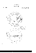
To all whom it may concern Be it known that I, JOHN MATTHEWS, J r., of the city, county, and State of New York, have invented certain new and useful Improvements in Pressure-Gages; and I do hereby declare that the following is a full, clear, and exact description of the same, reference being made to the annexed drawings, making a part of this specification, in which- Figure I is a back view or elevation. Fig. II is a front view. Fig. III is of a part in detail, and similar letters refer to similar parts throughout.
My invention consists in certain improvements in instruments for ascertaining the pressure of gases and fluids, and is chiefly designed for a steam pressure or vacuum gage.
This improvement belongs to that class wherein the elasticity of metals is employed to be acted upon and give the indications. Of these the aneroid barometer, and a gage wherein the metal is formed like a hollow bent spring are examples. Defects are found in these, and especially in the last named, which is the form of the kind generally employed for steam purposes, and those defects are as follows: First, the solder used for joining the edges of the plates together frequently cracks, and becomes thereby leaky, and this of course renders the gage useless; secondly, expansions and contractions by varieties of temperature of the weather affect the indications; thirdly, liability to freeze up in cold weather.
In order to give the curve to the hollow spring the sheet of metal forming the inner side must be less in length than the outer one; consequently every time that pressure is applied which tends to straighten out the spring, the metal is strained at the inner and outer joints, and this gradually efi'ccts its fracture. The water which is collected as the steam condenses fills up the lower end of the spring and there remains, as it cannot be emptied out, and hence in frosty weather, as before mentioned, the gage is rendered useless. All these difliculties are obviated by my improvement. The means by which I overcome the disadvantages named above, is by the peculiar formation of the metallic indicating chamber or vessel. This consists of an irregularly shaped tube without seams or joints, and the met-a1 so distributed that contraction and expansion by varying degrees of temperature has no injurious or destructive effect.
By an inspection of the expansive tube at A. Fig. I, it will be seen that wrought metal having that shape could not be formed out of a single piece, and a casting would be equally impossible since it could not be obtained thin enough for the purpose, and it would besides be very difficult to withdraw the core. I therefore employ the electro galvanic process for depositing the metal upon a core of some material fusible at a low temperature, such as stearin, wax, or of alloys whose melting point is at a low heat, or other substance which could be dissolved by acids &c. The shape of this expansion vessel is that of a tube having olfsets at one side of the column, in the form of hollow plates as shown at (b). The lower part of the tube is fixed to the dial plate, and has a screw coupling to connect the steam or other conducting pipe,the upper end of course being closed. The effect of expansion or contraction by changes of temperature merely, is simply either to elongate or to shorten the tube, because the sum of the surfaces (0) and (0) is only equal to the vertical surface (d), the lateral expansion producing no effect to deflect the tube, for it is by deflection only that the indications of pressure are to be obtained.
Now by forcing steam or other fluids into the tube the effect will be to expand or press apart the horizontal portions of the oflsets (b) and thus the inner side (0) of the tube becomes elongated, while the outer one (d) remains stationary. This elongation of one side produces a deflection of the vessel in the direction shown by the dotted line Fig. I, and the extent of this deflection measured at the top from the point of beginning, or zero, is the sum of the several amounts of spreading in the offsets. If the line joining these two points were divided into equal parts it would form a scale of pressures required to produce deflections to those several points. In ordinary practice however the motion would be so small as to require too fine a division of the scale, and therefore a long pointer operated by a shot lever or rack work is preferable as shown on the reverse of the dial plate, Fig. II. The pointer may however be dispensed with, where the expansion vessel is made of great length, or a long finger may be directly attached. It will now be seen that water cannot accumulate in the vessel, because it stands vertically and any accumulation in the pipe can always be blown out. Neither can there be a rupture of any part so long as the pressure is not carried beyond the limit of elasticity and power of cohesion of the metal.
The gage is put in operation by attaching a steam pipe leading from the boiler to the screw coupling at the bottom of the expansion tube, the dial being first attached to some fixed support. The ofl'sets are shown as all of a size. I do not however purpose to confine myself to the precise shape given in the drawings, but to vary it if required. One good form, where very considerable range of motion would be of JOHN MATTHEWS, JR.
Witnesses:
I. P. PUSSON, S. H. MAYWAM
This page has paths:
- Inventors and Patents Stephanie Armijo