Fisher H. Lippincott Patent
FISHER H. LIPPINCOTT, OF PHILADELPHIA, PENNSYLVANIA, ASSIGNOR TO THE AMERICAN SODA FOUNTAIN COMPANY, OF TRENTON, NEW, JERSEY.
SODA-FOUNTAIN.
SPECIFICATION forming part of Letters Patent No. 670,793, dated March 26, 1901 Application filed April 1. 1899- To all whom it may concern.-
Be it: known that I, FISHER H. LIPPINOOTT,
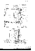
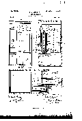
a citizen of the United States, residing in the city and county of Philadelphia, in the State of Pennsylvania, have invented certain new and useful Improvements in Soda-Fountains, of which the following is a full, clear, and exact description, reference being had to the accompanying drawings, of which- Figure 1, Sheet 1, is a longitudinal vertical section of a soda-fountain in which my invention is embodied. Fig. 2 is a side elevation, enlarged and partly in section, of the syrupjar-containing frame detached, with the jar therein. Fig. 3, Sheet 2, is a full front elevation of the soda-fountain,of three compartments for syrup-jars, in one of which the said jancontaining frame is in place within the compartment. In the second the frame is withdrawn, its bottom resting upon the table upon which the fountain stands, and the said frame has been entirely removed from the third compartment. Fig. 4. is a full section, as on line 4 a, Fig. 1. Fig. 5 is a full section, as on line 5 5, Fig. 1.
This invention relates to that class of sodafountains having one or more compartments for the reception of syrup-jars, which compartinents are open in front, and the jars are inserted and withdrawn longitudinally therefrom.
The object of the invention is to provide a construction that shall facilitate the insertion and withdrawal of the jars and at the same time to secure certain other advantages hereinafter mentioned.
The leading feature of the invention comprises a jar-containing frame having front and side walls and a bottom or support for the lower end of the jar, which frame is connected to the sides of the compartment of the fountain by means of pivoted bars in such manner that when it (the said frame) ispulled forward it, with the contained jar, may be entirely withdrawn from the compartment to a convenient position for removal of the jar or the refilling of the same with syrup and the frame and jar then be conveniently returned to the original position within the said compartment, all as hereinafter set forth.
Other features of my invention relate to de- Serial No. 711,395. (No model.)
tails of construction, all of which will be duly pointed out.
Referring now to the accompanying drawings, forming a part of this specification, and
which illustrate a soda-fountain with three compartments for as many syrup-jars and show a form of my invention which I believe to be the most desirable, 1 is the exterior casing or frame of a soda-fountain of well-known type, having the usual receptacle 2 for ice and, forward thereof, spaces or compartments 3, open in front, for the reception of syrupars.
i is a jar-containing frame that is formed of two sides 4:, a front face portion 4*, which I usually make of suitable ornamental material or materials to correspond with that of the casing of the fountain, and a bottom portion a". This frame is of suitable dimensions to neatly receive a syrup-jar 5, which is insorted by way of the open top of said frame.
In order to retain the rear end of the jar and aid in maintaining the latter in the required vertical position, I extend from the sides 4 of the frame a U-shaped strap 4.
3 represents the sides of the compartment 3, which latter is adapted to receive the frame at and its contained jar. These sides in the present instance project forward beyond the bottom 1 of the fountain-casing and beyond the one of the uprights 1 of the latter which supports that end of the said bottom, as seen in Fig. 1. The said coinpartments sides 3 are formed of plates of metal rigidly secured to the casing of the fountain .by suitable means-as, for example, by angle-bars 6 at the upper ends, having vertical grooves 6 for the reception of the plates, said bars being fastened to the depending front part 1 0 of the casing l by means of through-rivets 6 The rear part of the lower ends of the. sides or plates 3 rest in vertical grooves 7 in lugs 7 of a plate 7, that is riveted to the bottom 1 of the casing, they (the said sides) being 5 secured to plate 7, as by rivets 7, Fig. 1, extending through the said lugs 7 On the exterior of each of the'sides of the jar-frame 4 are pivoted, on studs 8, projecting from the latter, the upper ends of two similar bars 9 9 whose lower ends are pivoted on studs 10 of the compartment sides 3.
The bars of each set are parallel and extend pasteach other for a portion of their length when in the position shown in full lines in Fig. 1.. The said bars of each set are in different Vertical planes, so that the one may pass the other when the frame 4 is withdrawn from or returned within the compartment, they being offset by blocks 11 at the upper ends of bars 9 and the lower ends of bars 9 as seen in Figs. 4 and 5.
The syrup-jar is provided with a suitable faucet, not necessarily, however, of the kind or located as shown. I have, however, devised a faucet construction (shown in the drawings) that is especially well adapted for use in connection with my present invention and which I will proceed to describe, but will not claim herein, as the same will form the subject of an application for Letters Patent to be filed simultaneously with this application for my present invention. Said construction (omitting some minor details) is as follows: Extending vertically through the syrup-jar is a vertically-slidable rod 12, hereinafter termed the faucet-rod, whose upper end passes through a guide-aperture in the top plate 5 of the jar and whose lower end extends into what may be termed the faucet-nozzle 13 in the lower end or bottom of the jar, adjacent to the forward end of the latter. This nozzle consists of a tube or bushing 13, which is inserted and secured within an opening in the bottom of the jar. The internal diameterwof this nozzle is larger than that of the faucet-rod, and the latter has projections 13 for guiding its lower end in the nozzle. The lower end of the nozzle is seated in and secured to a cup 14, that extends through an opening in the bottom 4 of the jar-frame and is provided at the top with a circumferential flange 14*, that rests upon the top of said bottom. The cup 14 has an exit-opening 14 in its bottom, in which I usu-,
ally insert a lining 14, of india-rubber or other suitable yielding material.
For insuring a tight joint the lower end of the faucet-rod is made tapering, as seen, and is adapted to seat itself in the aperture in the lining 14, and thus effectually close the said opening when the faucet-rod is in the depressed position seen in Figs. 2 and 4. When the said rod is raised, the aperture 14 will be opened and syrup will be allowed to escape from the jar to be received in a glass placed beneath the exit.- It will be obvious that in this construction the faucet-rod must be operated from the outside of the jar-containing frame. lhave shown a convenient means for doing this, as follows: On the upper end of said rod is a disk or projection 15, under which takes the free end of a horizontal arm 16, that is connected to the upper end of a vertically-slidable bar 17, whose lower end is pivoted to the inner arm of a bell-crank lever 18, that is pivoted Within a recess 19 in the inner side of the front 4 of the jar-frame 4. The stem 20 of an external push-button 2O impinges against the other or vertically-depending arm of said lever 18.
By pushing in the button the faucet-rod will be raised through the described connections and syrup will be permitted to escape through the exit-opening 14. Upon releasing the button the rod will descend by its gravity andclose the said opening, at the same time returning the push-button, &c., to its original position.
'Thejar-containing frameis detachablysupported at the bottom in a manner not to interfere with the ready withdrawal and return of the said frame and contained jar, as hereinafter described. I provide a suitable support, to this end, consisting of a ledge projecting from the bottom 1 of the fountain-casing, such ledge being in the present case in the nature of a lug 21, depending from the aforementioned plate 7, to-which the lower ends of the sides 3 of the jar-receiving compartments are secured. In the top of this ledge is a groove 21, and the rear end of the bottom 4 of the said frame is turned downwardly, said downturned end forming a flange which is seated in the groove when the frame is in the position shown in full lines in Fig. 1-that is, when the syrup-jar, &c., is within its compartment of the soda-fountain. By this means the jar-containing frame is not only supported at the bottom, but is prevented from slipping forwardly off the said support. This downturned end of the bottom of the jar-frame thus resting upon the ledge, which latter and said downturned end extend immediately below the frame and the entire width of the latter, serves also to prevent the ingress of insects into the compartment. I sometimes insert in a groove g in the underside of the downturned end of the jarframe bottom a strip s,-of india-rubber, in order to secure a tight joint in the groove 21 of the ledge or lug 21 and also to serve as a cushion for the bottom of the jar-frame when the latter is withdrawn and brought to rest upon the table on which the fountain stands, as hereinafter described.
It will be observed, looking at Fig. 1, that when the jar-containing frame is in place within its compartment the upper ends of the pivoted bars 9 9 are in a vertical plane to the rear of the vertical plane occupied by the lower ends of said bars, and thus the said ends, and consequently the frame, to a higher level when they are drawn forward, as hereinafter described. It will also be seen that the upper edge of the front of said frame has a projection 9, that stops against the depending front 1 of the fountain-casing, and limiting the inward projection of the said jarframe prevents tipping back of the latter.
Having now described the construction of my invention, I shall proceed to explain the mode of operation thereof. The parts being in the position shown in the full lines of Fig. l and it being desired to remove the syrupjar for the purpose of replenishing the same or to substitute a filled jar for the empty one, the jarframe is drawn outwardly by inserting the fingers of one hand back of the projection p of the front wall of the frame (which is notched out or offset at p for that purpose) and, if necessary, the bottom of the frame is supported and drawn forward by the other hand. As the frame moves forward the bars turn on their pivots, those of their lower ends connected to the fixed sides of the compartment being the fulcra, and, consequently, by reason of the upper ends of said bars being to the rear of the vertical plane of their lower ends, the frame will rise and carry the downturned end of the bottom 4 from the groove 21 of lug 21. The frame being drawn farther forward, it will descend, always keeping the vertical position, until it is finally allowed to rest upon the table 22, as shown by dotted lines in Fig. I, or is stopped by some other suitable support. The syrup-jar may now be removed vertically from the frame, the aforesaid arm 16, that takes under the projection 15 on the top of the faucet-rod, being hinged to the upper end of rod 17, so as to permit the removal and insertion of the jar.
I remark that while I prefer to use the two sets of parallel bars 9 9 a single bar for each side may be employed, with, however, the disadvantage that the frame and its contained jar would not always be mechanically maintained in the vertical position, but would have to be so maintained when withdrawing from the compartment by the hands or other means.
Having thus described the construction and mode of operation of my invention, I claim as new and desire to secure by Letters Patent 1. In a soda-fountain of the class recited, the combination witha casing, of a syrup-jarcontaining frame hingedly connected to said casing and normally lying therein, a grooved supporting-lug carried by the casing, a flange carried by said frame and coacting with said lug, and a cushioning-strip carried by said flange and fitting in the groove of said lug when said flange is positioned on the latter.
2. In a soda-fountain of the class recited, the combination with a casing, of a syrup-jarcontaining frame hingedly connected to said casing and normally lying therein, a grooved supporting-lug carried by the casing, a flange carried by said frame and coacting with said lug, a cushioning-strip carried by said flange and fitting in the groove of said lug when said flange is positioned on the latter, and a stop carried bythe containing-frame for limiting the inward projection of the latter into the casing.
3. In a soda-fountain of the class recited, the combination of the syrup-jar-receiving frame, having the sides, front, and downwardly-turned bottom, the bars having their upper ends pivoted to the sides of said frame, and their lower ends to the sides of the compartment of the fountain adapted to receive the frame and its contained jar, the support having the groove, or the like, adapted to re ceive the said downturned bottom of the frame, and a suitable stop for limiting the inward projection of the latter, substantially as and for the purpose set forth.
4. In a sodafountain of the class recited, the combination with a casing, of a series of plates removably secured therein for dividing the easing intoa series of syrup-jar-receiving compartments, a containing-frame arranged in each of said compartments, a series of bars pivotally connected to each of said frames and said plates, whereby said frames are capable of being swung into and out of the compartments, and means whereby each of said frames is held in detachable engagement with the casing when projected therein.
5. In a soda-fountain of the class recited, the combination with a casing provided atits front with an opening, of a series of grooved securing-irons arranged at the top of said opening, a series of grooved lugs also arranged at the bottom of said opening, a series of plates fitting in said irons and lugs and adapted to divide the easing into a series of syrup-jar-receiving compartments, a containing-frame arranged in each of said compartments and capable of being swung into and out of the same, and means whereby each of said frames is held in detachable engage ment with the casing when projected therein.
6. In a soda-fountain of the class recited, the combination with a casing provided at its front with an opening, of a series of grooved securing-irons arranged at the top of said opening, a series of grooved lugs also arranged at the bottom of said opening, aseries of plates fitting in said irons and lugs and adapted to divide the casing into a series of syrup-jar-receiving compartments, a containing-frame arranged in each of said compartments and capable of being swung into and out of the same, a flange carried by said containing-frame, and a lug carried by the easing and with which said flange coacts, whereby each of said frames is held in detachable engagement with the casing when projected therein.
In testimony whereof I have hereunto af fixed my signature this 11th day of February, A. D. 1899.
FISHER H. LIPPINCOTT.
Witnesses:
WALTER O. PUSEY, JOSHUA PUSEY.