Describing Professional Processes with Informal BPMN Diagrams
By Shalin Hai-Jew, Kansas State University
Business Process Model and Notation (BPMN) is “the de-facto standard for representing in a very expressive graphical way the processes occurring in virtually every kind of organization one can think of” (Chinosi & Trombetta, 2012, p. 124). These also may be executable visuals, with backend logics that enable event simulations. And yet, for its high profile in other domains, BPMNs are not that widely known in the higher education space.
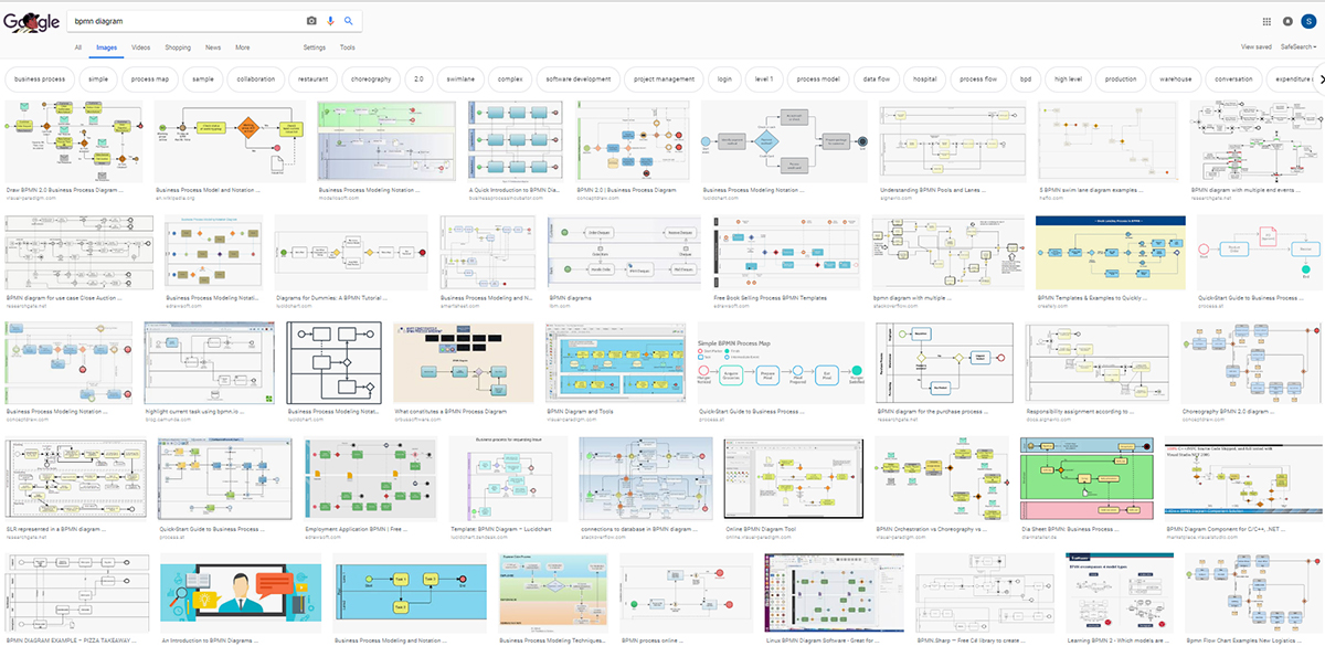
At first glance, BPMN diagrams look somewhat more complex than a flowchart, with more complex information. These seem to show multiple processes related to a particular business process ongoing at the same time. There is also something of swimlane diagrams in these visuals. A search for “bpmn diagram” on Google Search results in some sample images (Figure 1).
Figure 1. Some Image Results from “BPMN Diagram” on Google Search
This article will introduce basic and informal ways to get started drawing a BPMN diagram.
Getting Started
It helps to begin with the definition of a “business process.” This is defined as follows:
a set of one or more linked procedures or activities executed following a predefined order which collectively realize a business objective or policy goal, normally within the context of an organizational structure defining functional roles or relationships. A process can be entirely contained within a single organizational unit as well as it can span several different organizations. (Chinosi & Trombetta, 2012, p. 126).
A naïve approach begins with simply selecting a familiar work process and the necessary subtasks to achieve the work. One has to either know the process intimately or have access to others who have intimate knowledge of the process and is willing to take the time to share.
A work process in time. If one thinks about a process in time, it may help to begin by defining start and end points (Figure 2).
Figure 2. Identifying the Start and End Points
Then, add the intermediate points. (Figure 3).
Figure 3. Identifying the Start, Intermediate, and End Points
Then, the work may be broken down into tasks—described as processes and subprocesses. (Figure 4) The idea is to be as comprehensive as possible to include all the work. (Gaps will be noticeable when the work is actualized. One can always return to the BPMN diagram to update it with the actual required work.)
Figure 4. Defining Tasks (in Processes and Subprocesses, and Rough Sequences)
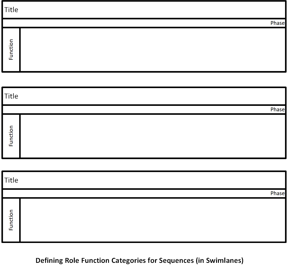
The work tasks may be clustered into role functions (categories) or phases or other forms of clustered relationships. (Figure 5)
Figure 5. Defining Role Function Categories for Sequences (in Swimlanes)
The elements may be brought together into one edited visual. (Figure 06) Note that this visual is for creating an interactive electronic book (e-book), and it was partially derived from an open-shared template from Trisotech, which offers some free downloadable templates that may be edited in Microsoft Visio. Here, the categories represent work phases. The level of detail is fairly general. There is no mention here of the setting of a stylebook with legal standards for the book creation and other basic details that would be critical to the work, for example. (Figure 6)
Figure 6. Creating an Interactive Electronic Book (in Three Phases) (as a BPMN diagram)
Depending on one’s mental models of processes, one can start general and go specific, or vice versa, or any old way that works.
There are many varieties of BPMN diagrams. Some show decision making junctures (chokepoints) where work has to be approved before follow-on work may be pursued. There are others where time itself is more explicitly defined. There are others with “gateways” where processes differ depending on decisions or states. This sort of visualization can be brainstormed and created at the same time.
Sometimes, these can be brainstormed with pen and paper or stylus and tablet. Others may prefer to start creating based on a template or an empty BPMN work space. Microsoft Visio Standard offers a basic BPMN work space, but Professional is required to access other variations. There are free downloadable templates from Trisotech and potentially other providers as well. (A workaround is to open a template, and copy and paste the respective objects. It is possible to create a stencil and shape set that provides the full visual functions of a BPMN diagram.) (Figure 7)
Figure 7. Using a BPMN Template Built into Microsoft Visio (Professional)
In Microsoft Visio Professional 2019, the BPMN template offers a wide range of related shapes in the left menu.
Figure 8. BPMN Basic Shapes in Microsoft Visio Professional 2019
Basic Parts of a BPMN Diagram
The sample visual only showcases some of the available features of a BPMN diagram. The sample should not be taken as more than one simple example, and there are many others available, with varying complexity.
So to recap, the basic parts of a Business Process Model and Notation (BPMN) includes the following general elements (with variations):
- Swimlanes to indicate particular sequences of processes
- A circle as a start point
- A circular indicator as an intermediate point
- A bolded circle as an end point
- A rectangle with rounded corners for tasks (processes)
- A rectangle with different line designs for sub-tasks (subprocesses)
- A diamond for “gateways” (with defined gatekeepers)
Dotted lines are used to show associations, and these may include arrows at the ends for directionality, or no arrows to show only the association. Data flows are indicated with checked lines. Solid lines with arrows show sequential processes with directionality in chronological time.
Various symbols indicate data stores and data types.
Closed boxes and rectangles indicate groups (in terms of the indicators inside the shapes).
There are text annotations and call-outs that may be applied to label visual BPMN diagrams. Further, “legends” may be included as well. These are usually read from left to right, and top to bottom.
The examples here are “flat” files that just capture the visual information. Coding may be applied to various BPMN diagrams to connect the work processes depicted with data stores and with particular functions and behaviors.
(Such visualizations may be expressed in code or on web-based collaboration systems, and these may update as new information is input. The Business Process Execution Language or “BPEL” and XML Process Definition Language or “XPDL” are languages that enable some of these functions.)
Why Create Data Visualizations of Work Processes?
Visualizing work processes can be a powerful way to interrogate understandings of professional roles, tasks, and process inter-dependencies and complexities, over time. As such, these understandings may enhance work planning, and the visuals may convey information in a compact way. Formalizing work processes enables ways to improve work processes for improve efficiencies. In informational technology contexts, errors like “interrupting conditions, deadlocks, infinite loops” may be identified in software programs (Chinosi & Trombetta, 2012, p. 124). Other inconsistencies may be identified.
Moreover, examining a graphical description of a process allows users to easily discover inconsistencies and / or differences in names or acronyms, infinite loops, non-terminating conditions and so forth. Using a formal graphical notation is the de facto standard choice to express a representation of a process which should be syntactically valid (thus assuring the consistence with the represented process) and having the same meaning as the (usually, natural language based) textual description of the process (Chinosi & Trombetta, 2012, p. 124).
The first version of BPMN was released in May 2004 followed by official specifications in 2006, and the second major release occurred in January 2011. Prior work in the visual description of workflows, UML Activity Diagrams, and other endeavors contributed to the development of BPMN. There are formalized professional certifications for building BPMNs, and an actual listing of the various elements is fairly complex.
In the research literature, researchers explain BPMN, offer critiques and identify shortcomings, describe various applications, share designed improvements, and other approaches.
While there are normative BPMNs that align with formal specifications (BPMN as an ISO/International Organization for Standardization standard) and semantic precision (and are used for automation and organizational advancement and work design), there are also non-normative ones, which may be used for local interests. In local workplaces, the semantics, for example, may vary from those applied in generalized applications.
A fun way to get started is to look at some classic examples depicting order fulfillment, pizza collaborations, Nobel Prize distributions, travel booking, email voting, and others (“BPMN 2.0 by Example,” 2010). These may be inspiring for spinoff analogical processes.
BPMN is a meta-model, with various types of sub-modeling beneath. Different exemplars vary in terms of how detailed and granular they are, and how real world or high fidelity the modeling is.
References
BPMN 2.0 by Example. Version 1.0 (non-normative). (2010, June). OMG dtc/2010-06-02. Retrieved Nov. 12, 2018, from http://www.omg.org/spec/BPMN/2.0/examples/PDF.
Chinosi M. & Trombetta A. (2012). BPMN: An introduction to the standard. Computer Standards & Interfaces: 34(2012), 124 – 134.
About the Author
Shalin Hai-Jew works as an instructional designer at Kansas State University. Her email is shalin@k-state.edu.
| Previous page on path | Cover, page 12 of 22 | Next page on path |
Discussion of "Describing Professional Processes with Informal BPMN Diagrams"
Add your voice to this discussion.
Checking your signed in status ...